Apollo 816 Linear Actuator Troubleshooting Guide: Mechanical & Actuator Solutions
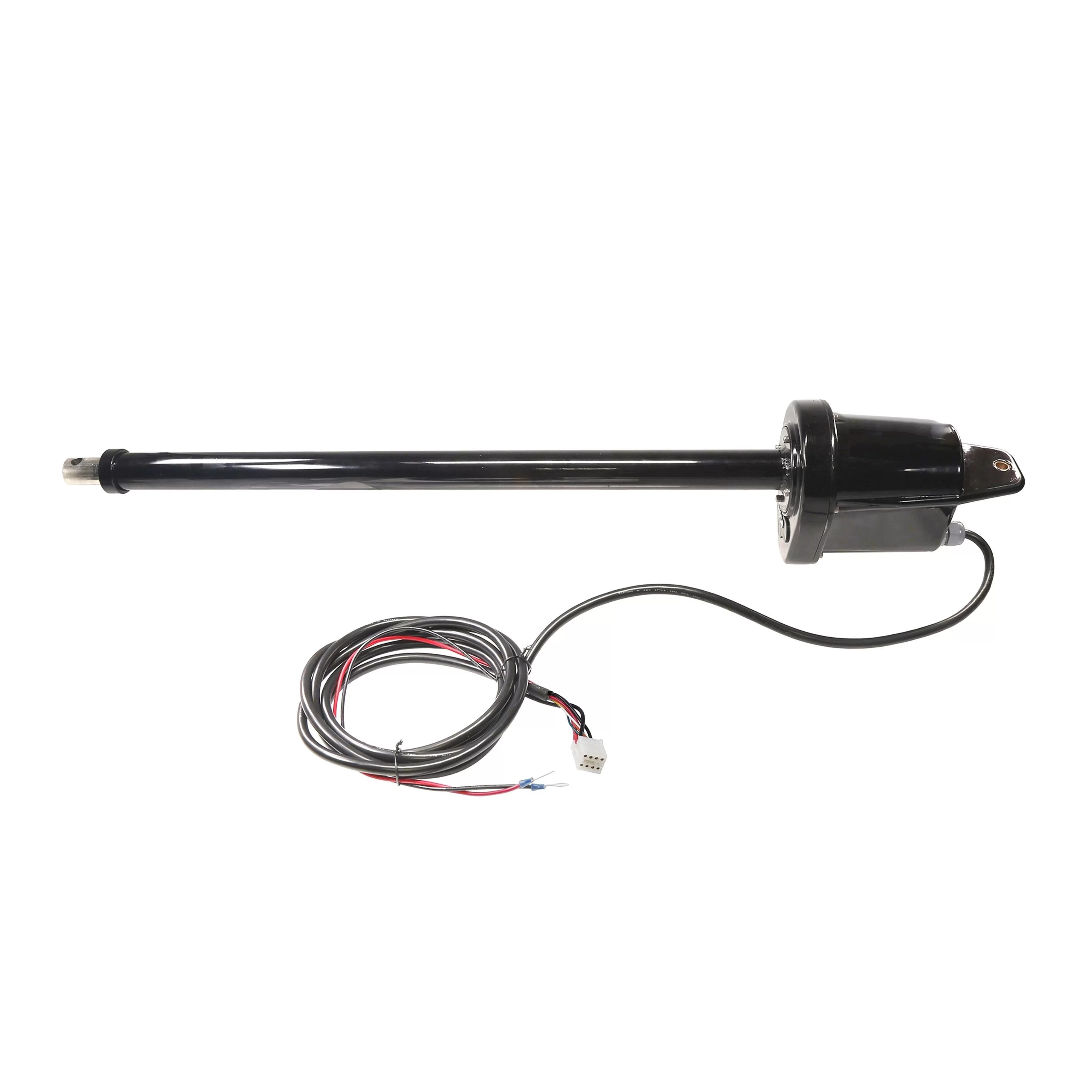
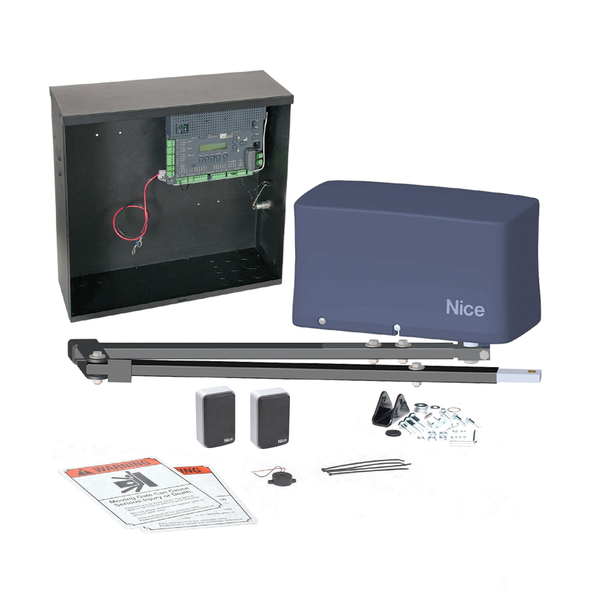
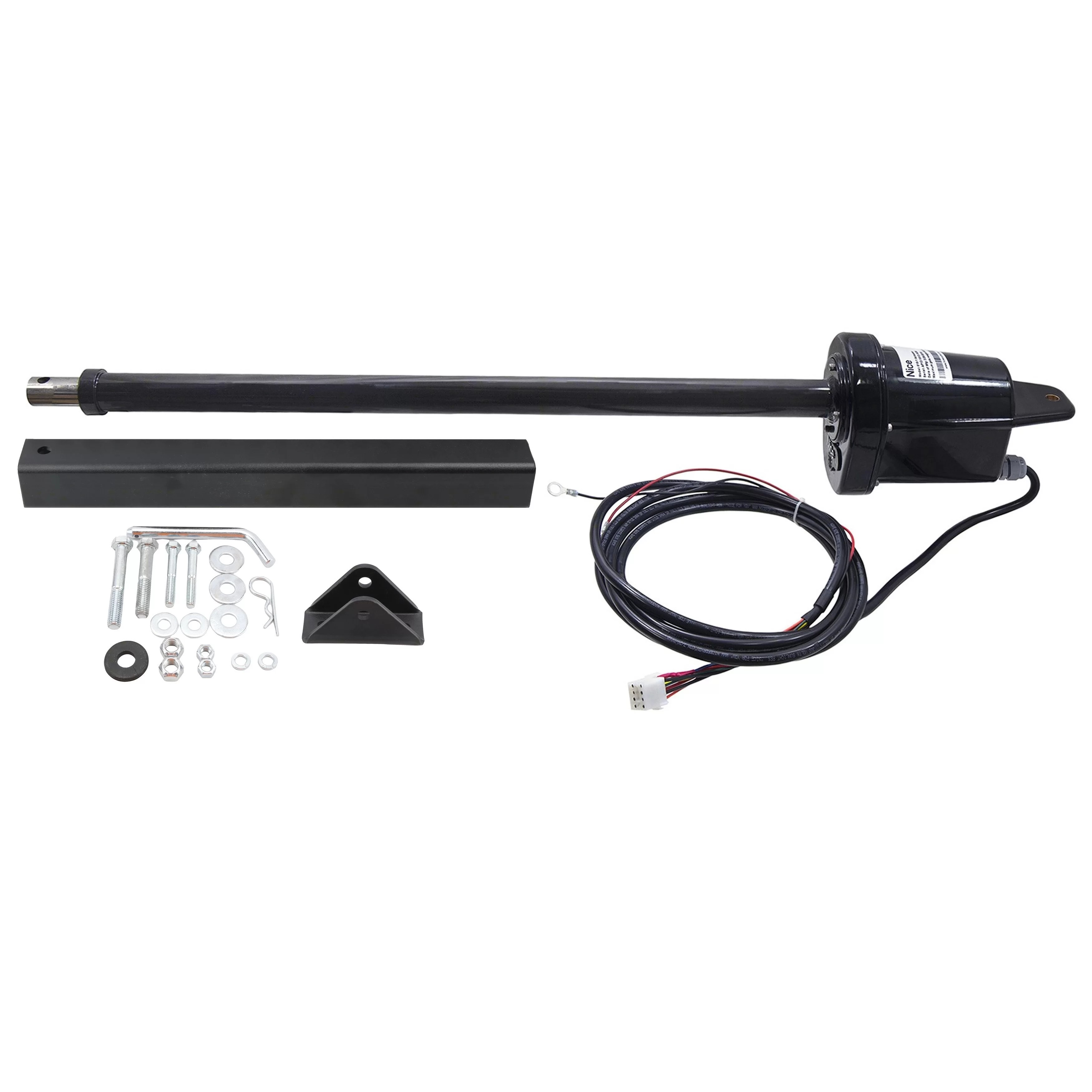
The Apollo 816 linear actuator is a key component in Nice Apollo swing gate operator systems, including models 1550-1K, 1550-ETL, 1551, 1650-1K, 1650ETL, and 1651 Nice Apollo 1550 Replacement Master Arm. This troubleshooting guide covers mechanical and actuator-only issues to help you maintain optimal gate performance. Whether you're dealing with an emergency manual release, excessive bounce, limit switch adjustments, or cable routing for dual gate installations, this guide provides step-by-step solutions to keep your gate operating smoothly.
How Do I Manually Release the Actuator in an Emergency?
In cases of power failure or emergency, the Apollo 816 actuator allows for manual operation via a quick-release mechanism.
Steps to Manually Release:
- Locate the hitch pin connecting the gate bracket to the actuator arm
- Remove the R-clip from the hole in the hitch pin
- Pull the hitch pin from the gate bracket and actuator arm
- Swing the gate open manually
Actuator Has Excessive "Bounce" or "Wobble" When Stopping
Excessive bounce or wobble when the gate stops is a common issue that is often caused by loose hardware at the actuator-to-pivot arm connection. This movement can be both annoying and potentially damaging to the gate system over time. The good news is that this issue is typically easy to identify and resolve with basic maintenance. The actuator arm is attached to the pivot arm with a bolt, washer, and lock nut. To fix the bounce and wobble issue, ensure the washer is positioned above the actuator flange, then tighten the lock nut securely to prevent movement or shifting when the actuator runs. Proper tightening of these components is essential to prevent excessive bounce or wobble when the gate stops moving. If the hardware is worn or damaged, replacement may be necessary to resolve the issue fully.
How to Adjust the Limit Switches on the Actuator
The 816 actuator features two limit screws located on the back of the actuator motor housing for fine-tuning the open and closed positions of your gate. Proper limit switch adjustment ensures your gate stops at exactly the right position when opening and closing, which is essential for both safety and convenience.
| Issue | Adjustment |
|---|---|
| Extend More (gate stops Too Early When Opening) | Turn EXTEND Limit Screw Counterclockwise |
| Extend Less (Gate Opens Too Far) | Turn EXTEND Limit Screw Clockwise |
| Retract More (Gate Stops Too Early When Closing) | Turn RETRACT Limit Screw Clockwise |
| Retract Less (Gate Closes Too Far) | Turn RETRACT Limit Screw Counterclockwise |
How Do I Get the Extension Tube Back to Factory Position?
If your extension tube has been disturbed or removed, following a proper factory reset procedure will ensure your actuator returns to its correct default position. This is particularly important after maintenance or if you've been experiencing erratic gate movement. The factory position ensures consistent and reliable gate operation. To reset the extension tube to the factory position, first turn off the Auto Close setting until you're finished with the procedure. Next, disconnect the arm from the gate bracket and remove both plugs from the back of the motor housing. Then turn each side toward its respective arrow until it bottoms out, being careful not to use an electric drill, as this could strip the threads on the limit block. After bottoming out, turn each side back 8 full turns (360 degrees) in the opposite direction of the arrow. Use the control board to retract the arm until it reaches the retract limit, then spin the extension tube until exactly 2.5 inches is exposed. At this point, the arm is in factory position, and you can reconnect it to the gate bracket and adjust the limits as needed.
How to Replace the Limit Assembly Tower
The limit assembly tower, part number A2038, controls the actuator's open and close limits and may need replacement if the limit switches fail or the assembly becomes damaged. This is a more involved repair that requires some mechanical aptitude and the right tools, but it can be completed successfully by following these steps carefully.
Tools Needed
- 3/16" Hex Key
- Wire Stripper/Cutter
- 3x Wire Crimp Connectors
- Socket Wrench with 3/8" Socket
Replacement Steps:
- Loosen the strain relief nut on the back of the motor housing
- Remove 6 screws on the rear housing (use 3/16" Allen key)
- Remove the rear housing: verify the brass, middle limit block is located toward the back of the housing (closest to the Phillips screws used for limit adjustments)
- Remove the Nice logo cover under the cover tube on the motor housing
- Remove both nuts on the front of the operator under the cover tube (use 3/8" socket)
- Remove the motor without cutting the wires
- Remove the remaining screws from the inner mounting plate
- Carefully remove the limit plate; the middle screw is not part of the limit assembly
- Manually unthread the limit block (pull back and out slightly, then drop down an inch or two)
- Cut the white limit wires
- Disconnect the smart sensor from the mounting plate and reconnect to the new mounting plate
- Install the new limit tower assembly, thread back on the limit block with springs on both sides of the limit block
- Tighten the nuts under the cover tube and snap the Nice logo cover back on
- Apply a new silicone bead to the rear housing and reassemble
- Tighten the strain relief
Gate Bracket Attachment - Bolt vs. Hitch Pin?
When attaching the gate bracket to the actuator arm, you have two options, each with distinct advantages depending on your priorities. Understanding the differences between these attachment methods will help you make the right choice for your specific application and security needs.
Bolt, Washer & Lock Nut
| Pros | Cons |
|---|---|
| More Secure, Tamper-Resistant | Slower Manual Release in Emergencies |
| Permanent Connection | Requires Tools to Remove |
Hitch Pin & R-Clip
| Pros | Cons |
|---|---|
| Quick Manual Release in Emergencies | Less Secure Against Tampering |
| No Tools Required | Pin Can be Removed by Anyone |
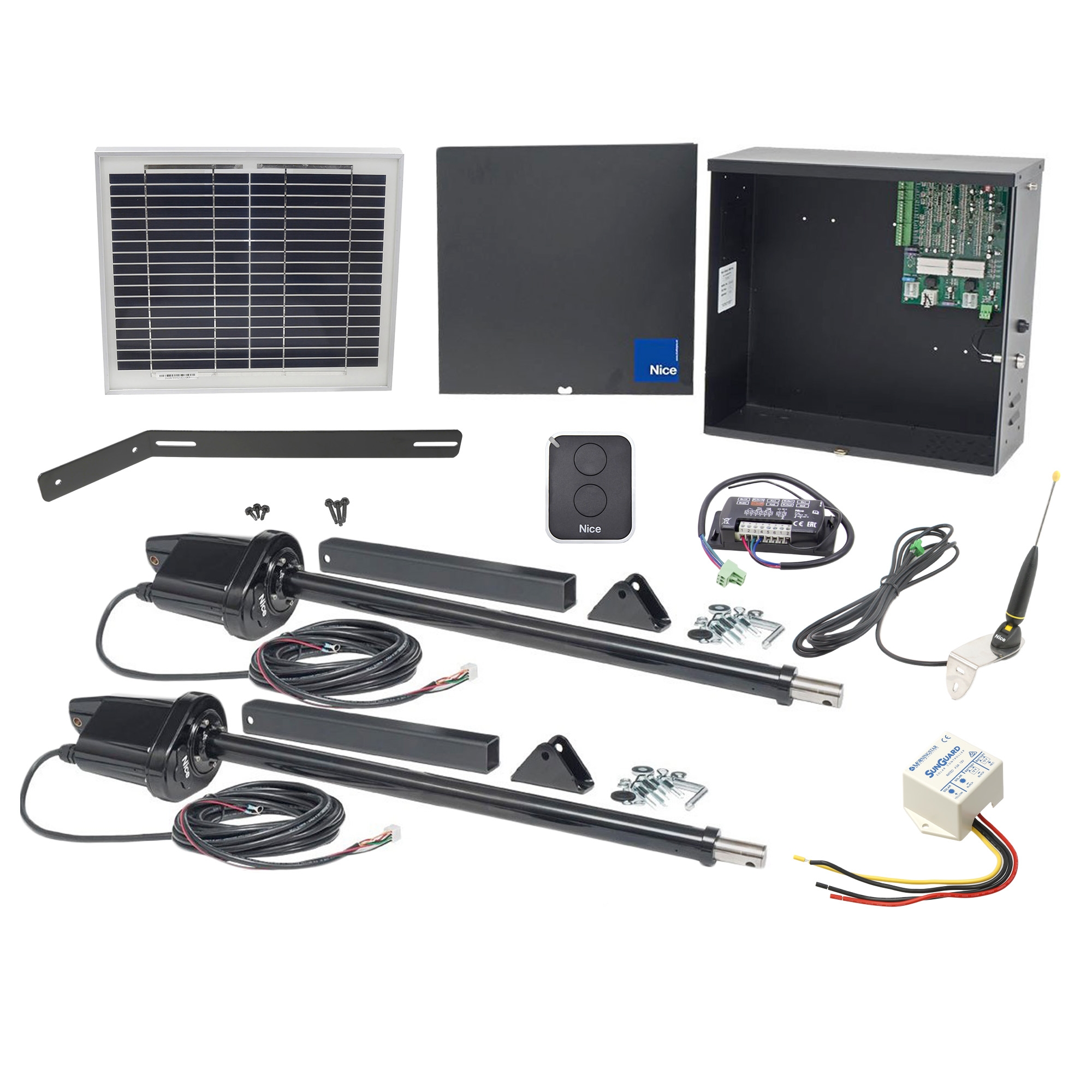
Cable/Harness Routing for Dual Gate Installations
Proper cable routing is essential for reliable dual gate operation and helps prevent signal interference, physical damage, and connectivity issues that can cause operational problems. Taking the time to route cables properly during installation will save you from troubleshooting headaches down the road.
Dual Gate Installation Steps:
- Dig a trench across the driveway deep enough to accommodate the longer harness cable from the actuator farthest from the control box
- Run the cable through the appropriate conduit and lay it in the trench
- Cover the trench and use an asphalt patch if needed
- Run the second cable into a hole (with rubber grommet) in the bottom of the control box
Shop Related Products and Replacement Parts
Looking to purchase replacement parts or upgrade your system? The following products are directly related to the Apollo 816 linear actuator and may help resolve your troubleshooting needs.
Related Articles
If you have any further questions, please reach out to our representatives. They are happy to help in any way they can!
Contact Us