Nice Apollo 635/636 Control Board Troubleshooting Tips
Setting up a gate opener can be tricky sometimes as there's brackets to install, measurements to be done, cables to wire, and on top of that dealing with a control board with all kinds of switches and ports. Mistakes happen, it's not always easy to set up a gate opener control board, and there's some common issues that happen when setting them up. Luckily, we've put together a list and some diagrams for the Nice Apollo 636 & Apollo 635 control board to get your gate openers up and running in just a few minutes.
Accessory Ports not functioning properly
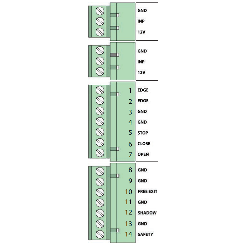
If your Apollo 1600 or 1500 gate openers accessories aren't working quite right, be sure to ensure that your connections are placed into the correct port and secured in place. To ensure that your accessories are connected properly, locate the input LEDs to the right of the ports (as shown below) and make sure that the lights are on. If they do not come on immediately, ensure that the LED Enable Button on the right side of the board is depressed to observe the LEDs. You do not need to turn them on, with power and a proper connection they will turn on automatically.
| Connector Grouping | Connection Purpose |
|---|---|
| Grouping 1 |
|
| Grouping 2 |
|
| Grouping 3 |
|
| Grouping 4 |
|
Emergency Bypass in the event of Gate Failure
If your gate is currently stuck or malfunctioning, even if the control box open/close gate button is locked, you can take a few easy steps to remedy this.
- Unplug the motor harness from the Master (or Slave) Connector and momentarily insert into the Emergency Bypass Connector to open the gate.
- Make sure to unplug the connector from the emergency bypass before the gate fully opens and binds.***
- In the event the motor is not disconnected quickly enough, the blue 15 amp fuse (in the bottom left of the board) will protect the circuit board from damage and should be replaced when the original problem is fixed.
***Using the emergency bypass connector only applies motor power to the actuator(s) to open the gate(s), with no limit function, closing function, or other setting options.
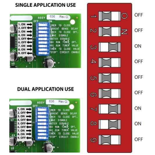
Timer to Close not Working
If your Timer to Close isn't working properly, ensure that the dip switch settings are aligned properly to the on/off positions for your needs. To adjust the timer to close, rotate clockwise to increase time before gate closes, and counter-clockwise to decrease time before gate closes. If program switch #3 is on, the gate must activate the open limit switch in order for the timer to close to operate. Follow the guidelines below to ensure your dip switches are in the proper positions and compare to the factory default settings.
| Dip Switch | On Off Settings |
|---|---|
| 1 - TIMER TO CLOSE - Automatically closes gate |
|
| 2 - CURRENT SENSITIVITY OPTION - Delays current sensing from start up |
|
| 3 - TIMER TO CLOSE OPTION |
|
| 4 - SLAVE DISABLE |
|
| 5 - MASTER DISABLE |
|
| 6 - MAXIMUM RUN TIMER OPTION |
|
| 7 - MAXIMUM RUN TIMER VALUE |
|
| 8 - TIMER TO CLOSE VALUE |
|
| 9 - OPEN, STOP, CLOSE CONTROL ENABLE |
|