How Does the Juno Slide Gate Opener Work? Juno Parts Diagram & Breakdown
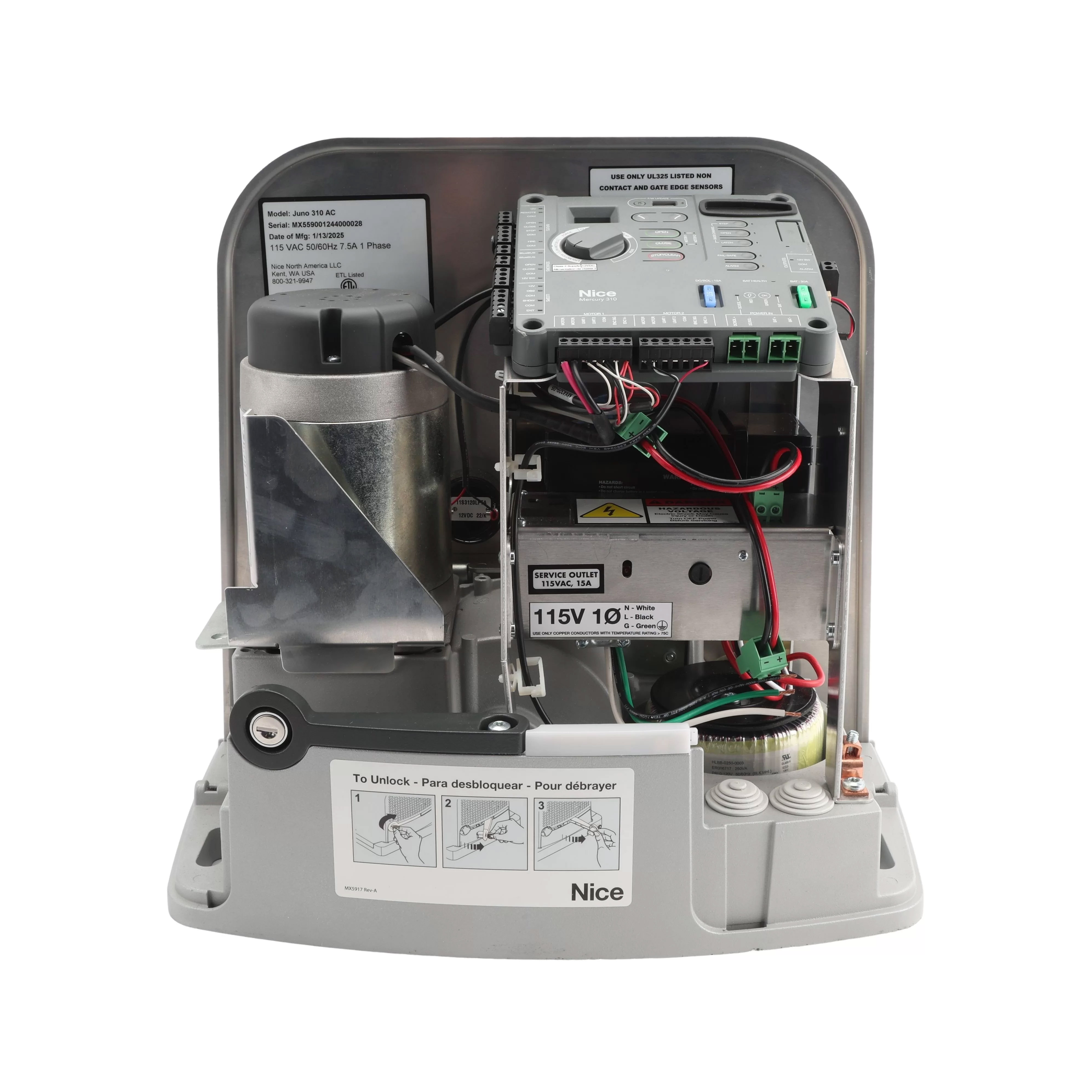
If you're trying to troubleshoot or repair a Juno Slide Gate Opener, it's important to first understand how all its parts work together. The Juno runs on a 12V DC motor and relies on the Mercury 310 control board to manage its movements and safety features. Knowing where each component fits (like the magnetic limit sensors, drive system, and entrapment protection) can make diagnosing issues much easier. This guide walks through the entire system, including a full breakdown of internal parts and how they interact during operation. Whether you're dealing with a motor issue or a sensor misalignment, this breakdown gives you a clear place to start.
How the Juno Operator Functions
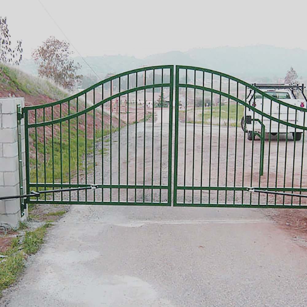
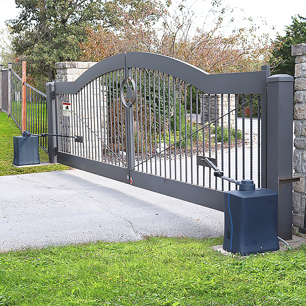
The Juno Slide Gate Operator automates the movement of a sliding gate using an electromechanical drive system powered by a 12V battery. When a command is received (from a remote, keypad, or sensor), the Mercury 310 Controller signals the DC motor to rotate. This action turns the main drive sprocket, which in turn moves the gate via a steel chain that is affixed at both ends to the gate structure. The gate’s position is monitored using two magnetic limit targets mounted on the chain. These are sensed by two stationary target sensors as they pass by. When one of these targets is detected, the controller knows the gate is at its fully open or closed limit and responds accordingly, either stopping the motor or beginning a deceleration ramp to ensure smooth halts.
In the event of an obstruction, the Inherent Entrapment Sensor (IES) built into the Mercury 310 detects abnormal current draw from the motor. This triggers a safety reversal to prevent injury or damage. Additional safety devices like photo eyes and edge sensors can be installed to meet UL325 standards. The system is powered entirely by a 12V DC battery. In AC-powered systems, this battery is charged through a built-in transformer and power supply. In solar-powered configurations, the Mercury 310 includes a Maximum Power Point Tracking (MPPT) charge controller, optimizing energy harvested from solar panels for off-grid use.
Altogether, the Juno Slide Gate Operator delivers precise, programmable, and safe automation for slide gate systems, with flexible power options and a modular design that makes it ideal for residential and light commercial installations.
Juno Slide Gate Operator Parts Breakdown
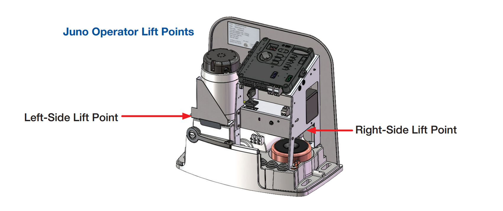
1. Left-Side Lift Point
Heavy-duty mounting holes on each side of the operator frame act as lifting handles or hoist points during installation. These structurally reinforced areas make it safe to transport and install the unit without damaging its internal components or outer housing.
2. Right-Side Lift Point
This opposing lift point complements the left-side anchor, allowing balanced hoisting of the unit. Proper lifting from these designated points prevents stress on the housing and internal structures, ensuring installation safety and stability.
3. DC Motor
The DC motor provides the mechanical force necessary to move the gate. Connected directly to the main drive sprocket, the motor converts electrical energy into rotary motion, which drives the chain system. This high-efficiency motor is engineered for durability, consistent torque, and long service life. It responds to precise commands from the Mercury controller, enabling soft starts, controlled stops, and smooth direction changes during operation.
4. 120VAC Outlet
This outlet is where AC power is supplied to the system in mains-powered models. It feeds into the power supply enclosure, from which voltage is regulated and distributed to the battery and controller.
5. AC Power Wires (Green, White, Black)
These wires deliver incoming alternating current from the 120V outlet to the toroidal transformer. Each wire is color-coded for grounding (green), neutral (white), and hot (black), and must be properly terminated for electrical safety and reliability.
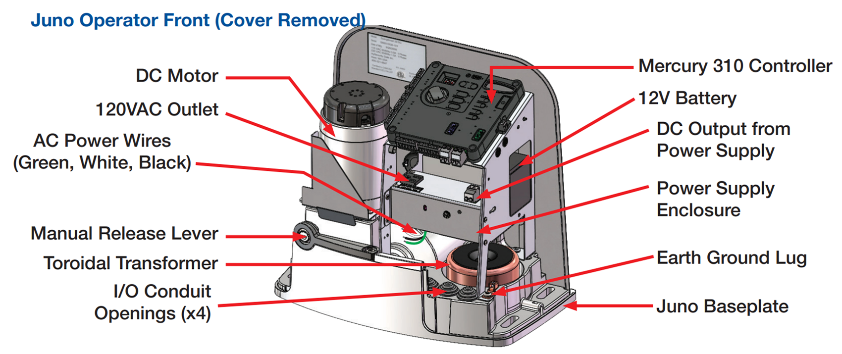
6. Manual Release Lever
Positioned on the front of the unit, the manual release lever allows the operator to disengage the motor drive, enabling users to manually slide the gate. This feature is critical during maintenance, emergencies, or power failures, allowing for secure manual access without tools.
7. Toroidal Transformer (AC Models Only)
The toroidal transformer is a low-noise, high-efficiency coil that reduces incoming AC voltage to a lower voltage level suitable for the DC system. Its circular core minimizes electromagnetic interference, making it ideal for sensitive electronics like the Mercury 310 Controller. It ensures stable power conversion, promoting consistent battery charging and safe gate operation.
8. I/O Conduit Openings (x4)
These four pre-drilled conduit entry points are located at the bottom of the baseplate. They allow for neat and protected routing of various wires, including AC power, low-voltage communication lines, and accessory inputs. Proper use of these openings ensures compliance with electrical codes and prevents moisture ingress.
9. Mercury 310 Controller
At the heart of the Juno operator is the Mercury 310 Controller, a powerful logic board that governs every action taken by the system. This controller interprets inputs from sensors, remotes, and safety devices, and it commands the motor’s operation based on programmed settings. It features easy-access function buttons, rotary selectors, and diagnostic LEDs to streamline configuration, limit setting, and troubleshooting. The controller also monitors motor current to detect obstructions and activate safety protocols.
10. 12V Battery
The system’s primary energy reservoir, this sealed 12V AGM battery powers both the controller and the motor. In AC systems, it is trickle charged by the internal power supply, while in solar models, it receives energy through an MPPT charge controller. The battery enables the gate to continue functioning during power outages or in off-grid environments, ensuring consistent access control.
11. DC Output from Power Supply
In AC-powered versions, the DC output board delivers regulated 12V power from the transformer to the system battery and controller. It provides the necessary voltage and current to keep the system running smoothly and the battery fully charged without overvoltage risks.
12. Power Supply Enclosure (AC Models Only)
In AC-powered Juno operators, this metal enclosure houses the power supply components that convert 120V AC mains power into 12V DC for system use. It includes the toroidal transformer and a regulated DC output board. The enclosure also serves as a protective shield against moisture, dust, and incidental contact.
13. Earth Ground Lug
This grounding point is required for safe system operation. It must be securely connected to a proper earth ground rod to dissipate static electricity and protect the equipment from voltage surges, particularly in lightning-prone areas. A properly grounded system enhances overall reliability and meets UL safety requirements.
14. Juno Baseplate
The Juno baseplate forms the foundational support structure for the entire gate operator. It houses the motor, transformer, controller, and conduit openings. It is precision-molded for strength and designed to bolt securely to a concrete pad or metal post mount.
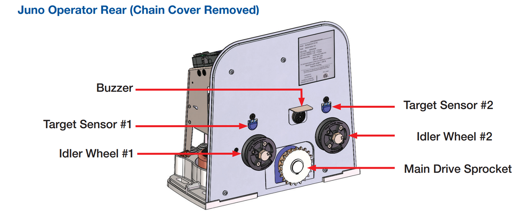
15. Buzzer
Located at the rear of the operator, the internal buzzer provides audible alerts to signal gate movement, warnings, or system faults. It emits distinctive tones to notify users during programming, gate operation, or in response to errors. This enhances both operational awareness and safety for pedestrians and vehicles in the gate area.
16. Target Sensor #1
Target Sensor #1 is positioned on the left side of the interior wall and detects the magnetic field from the limit target magnet as the gate approaches its fully closed position. It provides input to the controller for safe and accurate stopping of the gate.
17. Idler Wheel #1
Mounted on the left side adjacent to the main drive sprocket, this idler wheel guides and tensions the drive chain. It also carries the magnetic limit target associated with Sensor #1, helping define the closed position of the gate.
18. Target Sensor #2
Located on the opposite side of the chassis, Target Sensor #2 reads the magnet attached to Idler Wheel #2. It determines when the gate reaches its fully open limit and signals the controller to slow or stop the motor accordingly.
19. Idler Wheel #2
This component mirrors Idler Wheel #1 in function and design. It maintains chain alignment on the right side of the operator, while also holding the magnet that triggers the open gate limit via Sensor #2.
20. Main Drive Sprocket
This sprocket is directly coupled to the DC motor and plays a crucial role in the movement of the gate. As the motor turns the sprocket, it pulls or releases the chain that is attached to the sliding gate. The sprocket’s robust, toothed design ensures strong engagement with the chain, minimizing slippage and wear. It forms the core of the gate’s motion conversion mechanism from rotary to linear movement.
Contact Us
For more information on Juno Slide Gate Operators, check out our Resources Hub for Installation Guides, Mounting Methods and Options, Model Comparisons, and more! Not sure what you're looking for? Reach out to our incredible sales team who are knowledgeable and ready to help you with your Juno Installation.