How to Add a Mechanical Lock to Apollo Gate Openers
Manual gate latches and locks should not be used with any automatic gate opener system. Specific mechanical (solenoid) and magnetic locks are designed with automatic gate operators. The force applied to a manual latch or lock and the gate by the operator system may cause damage to the latch or lock, the gate, the opener system, and anyone nearby. Mechanical and magnetic locks designed for automatic gate opener systems connect to the control board. They will be unlocked and locked as the gate is commanded or authorized to open and close. A gate lock can be installed between two gates or between a gate and a fence post.
Mechanical Solenoid Locks for Apollo Gate Openers
Electric gate locks work with automatic gates by securing to the gate frame and the adjacent fence or to two gates. The lock is wired into the gate opener control box such that the lock disengages when the gate is opened via transmitter or keypad.
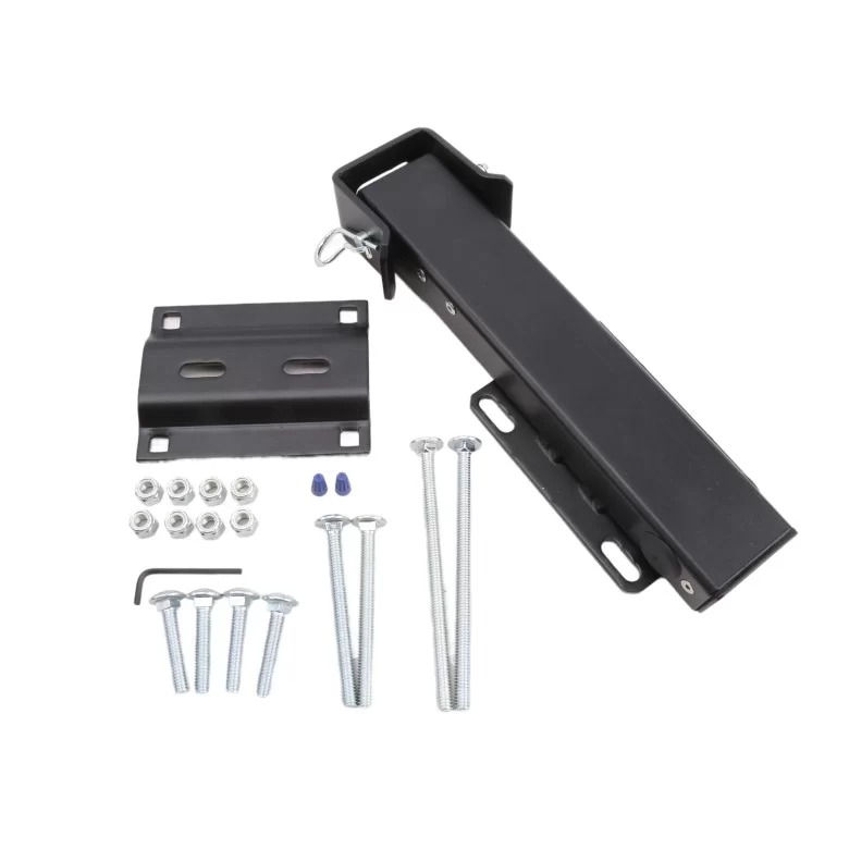
This Heavy Duty Solenoid Gate Lock is designed for all gate openers with a 1050 control board. The lock does not require continuous power, is ideal for solar gate opener systems, is black powder-coated, and can be installed right or left-oriented. The solenoid lock kit includes the lock housing, lock mounting bracket, strike bracket, strike pin with clip, a collection of bolts, lock nuts, an Allen wrench, rubber plugs, and a wire nut.
How to Install a Mechanical Solenoid Lock to an Apollo Gate Opener System?
For the gate lock to work properly, the gate must close firmly against the adjacent gate frame or the fence post. Before installation, you must adjust the close limit to position the gate in the desired closed position.
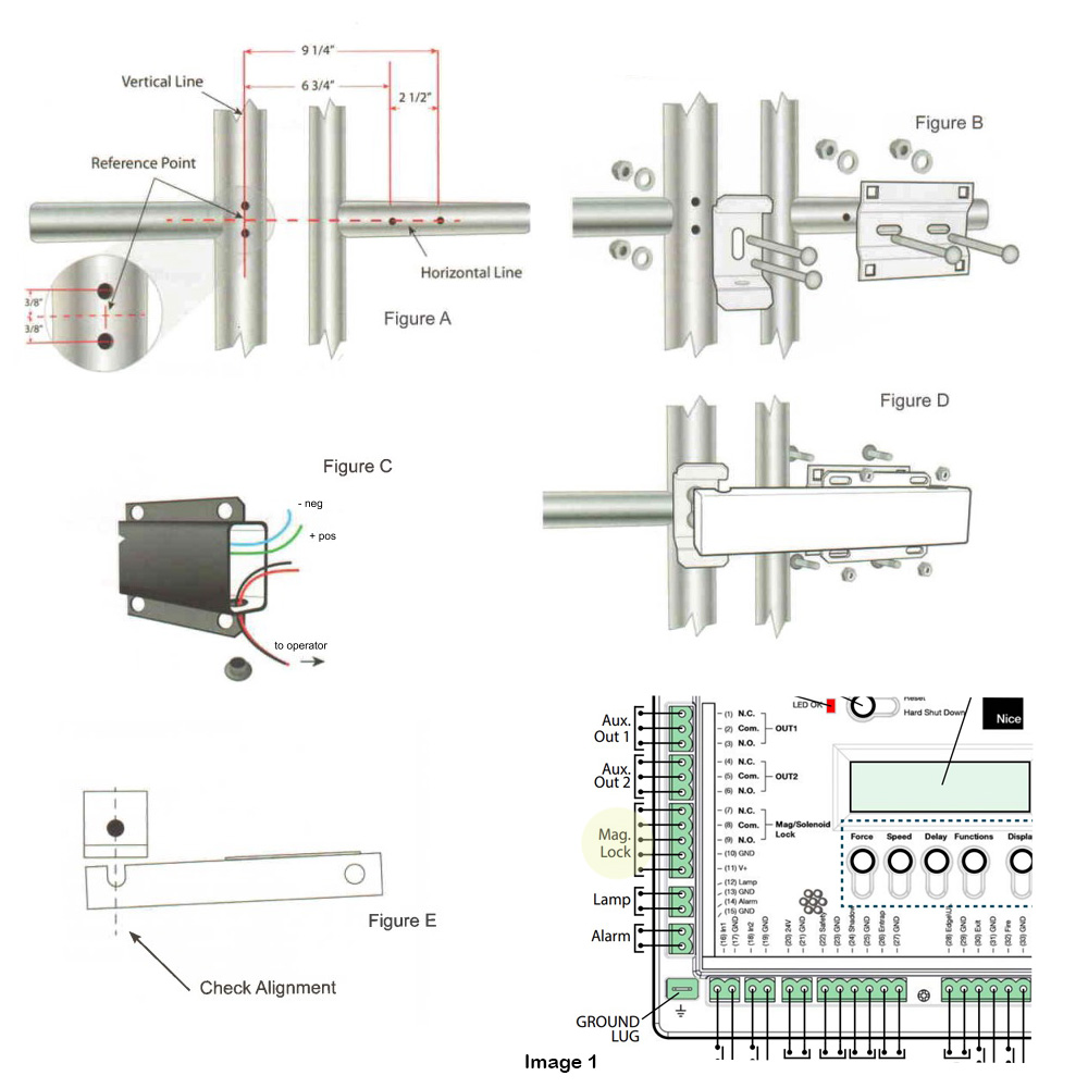
- Shown in Figure A: With a level, draw a horizontal line across the center of the gate rail and across to the receptor post or gate rail. Then, on the receptor post or rail, use a level to draw a perpendicular vertical line to create a center reference point for the lock mounting bracket.
- Shown in Figure A Close Up: On the receptor post, measure 3/8" above and below the cross reference point.
- Shown in Figure A: Measure and mark two points 6 3/4" and 9 1/4" horizontally from the reference point on the gate rail.
- Double-check the measurements and mount the locking bracket to the receptor post or gate rail and the strike bracket to the gate rail. Use a 1/8" drill bit to create a pilot hole and then a 3/8" drill bit to widen the holes for the 3/8" bolts. Note: you must drill through both sides of the rail.
- Shown in Figure B:Mount the strike bracket without the strike pin to the receptor post, but do not tighten.
- Shown in Figure B:Mount the locking bracket to the gate rail, but do not tighten.
- Shown in Figure C:Before mounting the electric lock, remove the bottom plug and end cap. Attach the green (+) and blue (-) wires to the wires leading to the gate opener control box. Do NOT connect wires to the opener system yet.
- Disconnect power to the opener by removing the motor plug(s) from the control board.
- Shown in Figure D:Mount the lock by aligning the holes on the bracket with the lock housing and tightening.
- Disconnect the arm from the gate.
- Shown in Figure E:Open and close the gate by hand to check the binding. If binding occurs, adjust the strike bracket and/or locking mounting bracket until there is no longer binding. Check for alignment of the strike pin with a slot in the lock housing and fully tighten the lock nuts on both brackets.
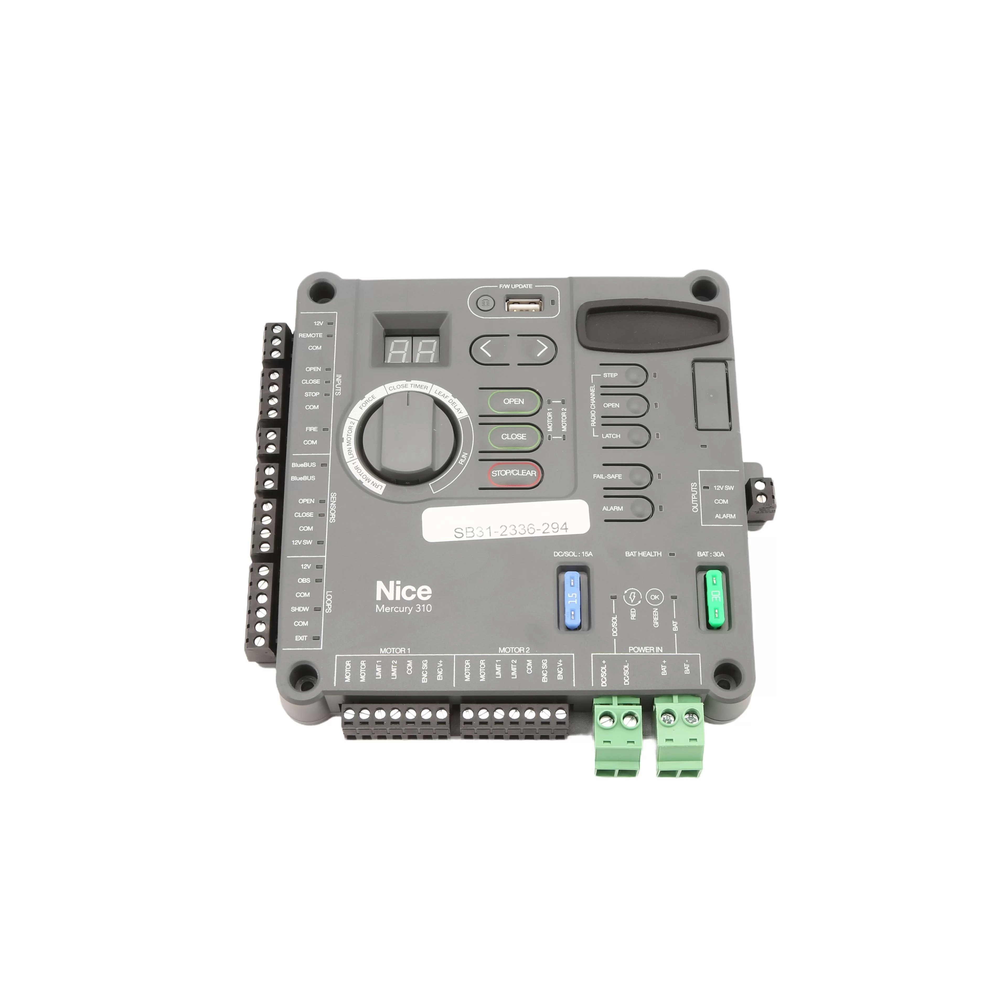
- Shown in Image 1:Attach the two wires from the electric lock to the leading wires. Check that the leading wires are connected to the correct terminals on the control board.
- Reconnect the opener arm to the gate and reconnect power to the opener by reconnecting the motor plugs.
- Initiate the operator to open and observe the lock to see if the lock pin retracts during opening and extends during closing. If the lock retracts and extends properly, install the strike pin with a clip or padlock. Power should only be applied during the opening cycle. All power to the electric lock should be off during the closing cycle or in the rest position.
- Reset the opener system's limit switches to ensure proper lock closure. After all adjustments have been made, tighten all nuts and cut off excess bolt length.
If you have further questions about Apollo Gate Opener products and accessories, please visit our Resources Hub for informational and instructional content or reach out to our friendly sales representatives. They are happy to help in any way they can!
Contact Us